
ER Diagram
View all tables and foreign key relationships in your schema as an interactive diagram. Right-click a database in the sidebar and select View ER Diagram, or use the menu bar View > ER Diagram.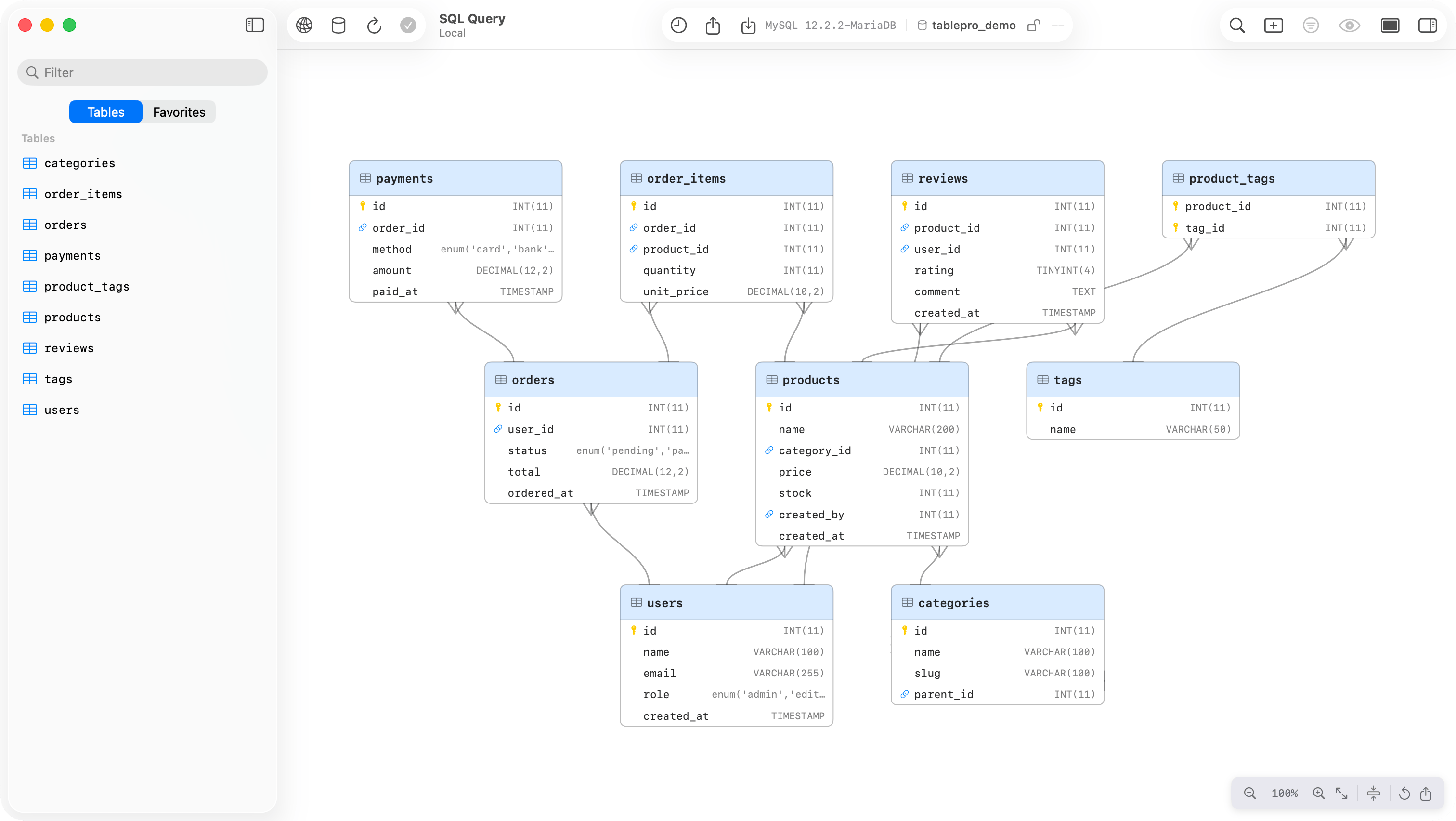
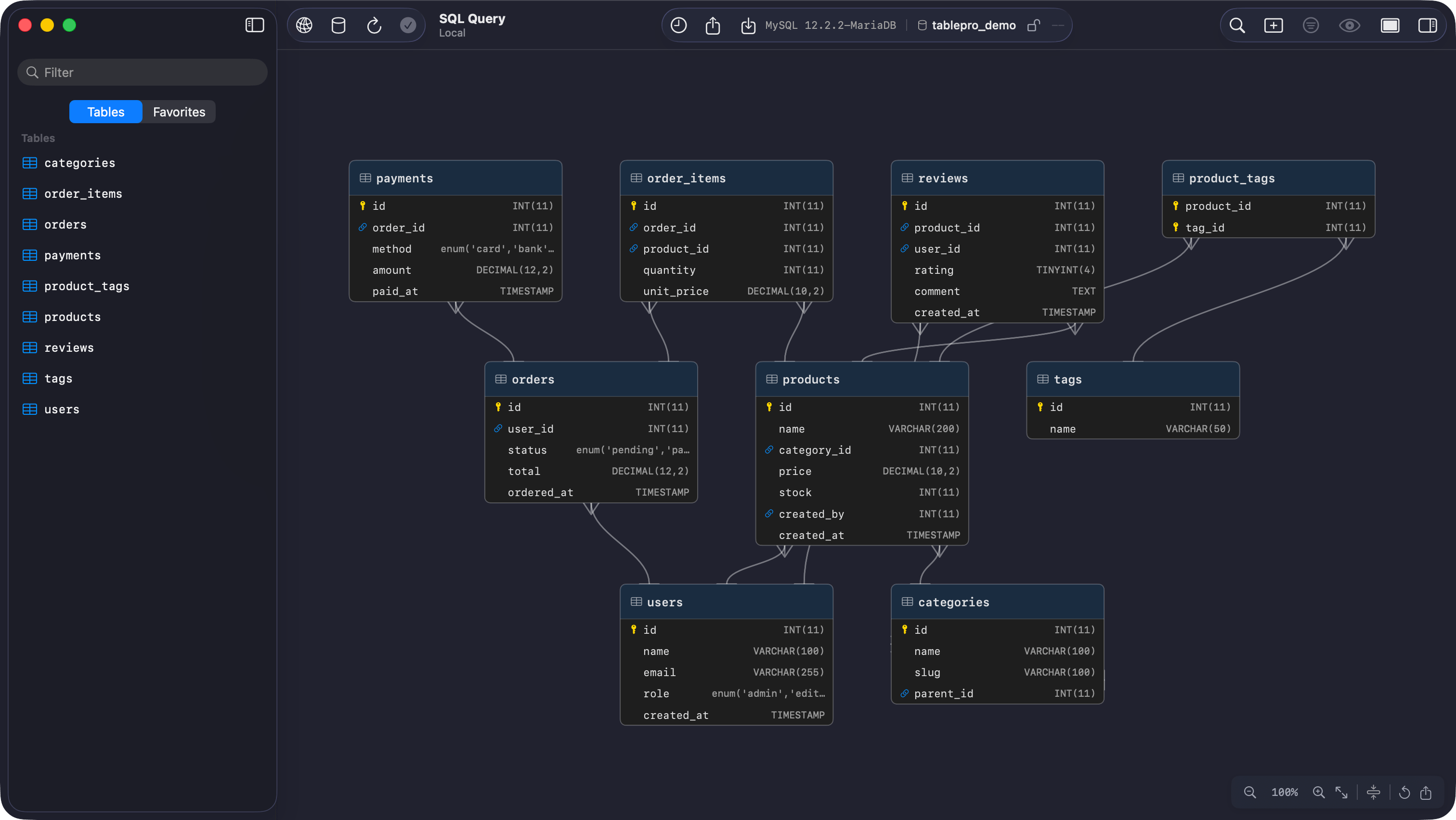
ER diagram showing tables and foreign key relationships
Layout
Tables are arranged automatically using a layered layout algorithm. Tables with foreign keys (child tables) are placed above the tables they reference (parent tables). Tables with no relationships are placed in a grid below. Each table node shows:- Header: table name with icon
- Columns: name and data type, with badges for primary keys and foreign keys
- Edges: lines connecting FK columns to their referenced tables
Navigation
Moving Tables
Click and drag any table node to reposition it. Positions are saved automatically and persist across sessions. Drag a table toward the edge of the viewport to auto-scroll the canvas in that direction. Click Reset Layout (the circular arrow button) to return all tables to their computed positions.Compact Mode
Toggle compact mode with the filter button in the toolbar. In compact mode, each table shows only primary key and foreign key columns.Edge Notation
Edges use crow’s foot notation:- A fork (three lines) marks the “many” side of the relationship (the table that holds the foreign key)
- A bar (single perpendicular line) marks the “one” side (the referenced table)
orders.user_id to users.id has the fork at orders and the bar at users.
Export
Click the export button in the toolbar to save the diagram as a PNG image. You can also pressCmd C to copy the diagram to the clipboard.
Database Support
ER diagrams work with any database that supports foreign key introspection:The diagram shows foreign keys defined in the current schema. Cross-schema foreign keys are included if the referenced table is in the same schema.